Airfoil Analysis
Goal
Prepare and analyze the aerodynamic characteristics of a wing profile in XFLR5: select or create a profile, compute Cl, Cd, and Cm across ranges of angles of attack, Reynolds numbers, and Mach numbers, and save the polar curves for subsequent aircraft analysis.
Step-by-Step Plan
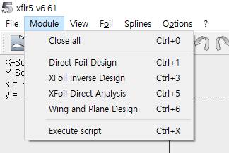
- Open the Direct Foil Design tab (Ctrl+1).
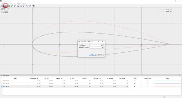
- Create a NACA profile (Alt+N) or load your own profile from a .dat file.
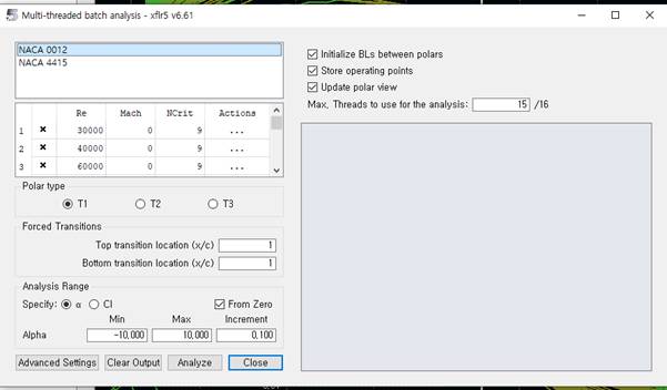
- Go to XFoil Direct Analysis → Analysis → Batch Analysis.
- Set the ranges: Reynolds numbers, Mach numbers, angles of attack (start, end, step).
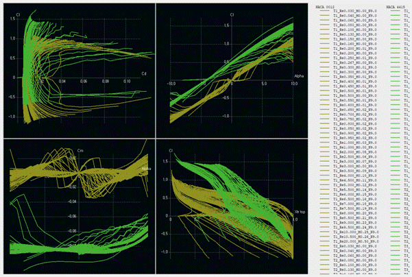
- Run the analysis and review the polar curves. Save the results.
Analysis Parameters — Summary
- Re (Reynolds number): defines the flow regime (laminar/turbulent) and model scale.
- M (Mach number): important at high speeds (compressibility effects).
- α (angle of attack): range used to build polars and find maximum efficiency.
Notes and Tips
Tip: For aircraft-level analysis, it is best to have polars for several Reynolds numbers (e.g., different flight speeds). This increases the fidelity of the final model. Note: If the profile is non-standard, verify the .dat file (number of points, ordering). Errors in the file lead to incorrect polar curves.
For the first stage, press Ctrl+1 or select Direct Foil Design from the tab panel. Then press Alt+N to create NACA profiles. For a custom profile, use the .dat loader (highlighted in red in the figure).
After defining the profiles, compute the aerodynamics in XFoil Direct Analysis. In the Analysis → Batch Analysis tab, set Re, M, and angles of attack. Aircraft analysis requires data for multiple Re values.